

H20 beams for formwork support the facing and pass fresh-concrete loads into the beam and support system. Therefore, their spacing depends on the facing, beam data, support layout and planned pour. Each later use also needs a check of the beam’s current condition.
A deck can contain the right beams and still have the wrong load path. For example, a crew may add secondary beams while leaving an overloaded prop grid in place. On a wall, a faster placing rate may change the pressure behind an unchanged facing.
We recommend treating each pour as a defined job with a released layout and a released set of beams. That joins the supply brief, the site checks and the next use. The final layout and loading limits must follow the project design and the named system’s current instructions.

H20 Beams for Formwork Start with a Defined Pour
Before work starts, define the concrete and the form to be built. State whether the work is a slab, wall or a special detail. Then identify the facing, the support system and the load cases that the designer has approved.
For a slab, the brief needs the pour zones, slab thickness and local changes in depth. It also needs the placing sequence, work loads and storage limits on the deck. For a wall, include the mix, the pressure model, the placing rate and the tie layout.
Next, link that brief to a drawing revision and the actual beam product. A change in the facing or support grid can reopen the layout check, even when the beam stays the same.
BS EN 13377 covers requirements, classification and assessment for prefabricated timber formwork beams. BS EN 12812 addresses falsework performance and general design. These give the buyer two distinct evidence needs: the beam’s product data and the design of the assembled support system.
Read the Beam Data on the Right Basis
A bending value, a shear value and a stiffness value answer different questions. Bending and shear concern resistance. Stiffness helps predict movement under load. Also check the permitted support reaction and the required bearing detail.
For example, Doka’s H20 top data list a bending moment of 5.0 kN·m and shear of 11.0 kN. The listed EI is 450 kN·m². Those figures belong to that named product. Our offered beam needs its own confirmed data and use rules.
Therefore, keep permissible values, design values and test results clearly labelled. Then match them to the load basis used in the layout check. A high breaking load from a test is not, by itself, a permitted site load.
A Slab Deck Has Three Linked Grids
The facing spans between secondary beams. Those beams then pass the load to the primary beams beneath them. The primary beams pass it to props or shoring towers. Each grid has its own spacing and its own governing check.
Doka’s Dokaflex system links beam and prop spacings to the floor load and layout. The practical lesson is to keep all three grids on one approved drawing. A beam spacing quoted without its facing and support case leaves part of the job undefined.
The Panel Sets the First Support Check
Start with the actual facing panel and its approved load data. Then check its thickness, bending direction, joint support and movement limit. The specified underside finish may also demand closer control of movement and joint steps.
However, a stronger beam beneath the panel does not remove the panel’s own span limit. Similarly, sound panels can still give poor results if their joints lose support or the props settle.
We recommend keeping the facing specification beside the beam grid on the pour drawing. That allows the site team to spot a panel change before it becomes a spacing change.
How H20 Beams for Formwork Collect the Slab Load
A secondary beam receives load from a strip of deck. For a regular interior bay under uniform area load, its surface-load share follows a simple relation:
Line load on a secondary beam = area load × its tributary width.
Here, tributary width means the strip of deck assigned to that beam. Edge bays, openings and irregular grids need their own load assignment. Also add member self-weight and any local loads required by the design.
The primary beam receives reactions from the secondary beams at their contact points. Those are discrete forces. An average line load helps track the total. However, the designer must check the actual force positions and support model.
Therefore, check beam contacts near an overlap, a deck opening or a moved prop. The total load can remain similar while a local reaction becomes more severe.
Why Closer Secondary Beams Leave the Concrete Load on the Props
Consider this isolated load-accounting example. Assume a fictional uniform surface load of 8.0 kN/m² and a primary-beam tributary width of 2.0 m. Compare secondary-beam spacings of 0.50 m and 0.40 m in a regular interior grid.
These are teaching inputs, not approved spacings or code loads. Member self-weight and local loads remain separate from this surface-load calculation.
| Surface-load measure | Secondary beams at 0.50 m | Secondary beams at 0.40 m |
|---|---|---|
| Assigned surface load | 8.0 kN/m² | 8.0 kN/m² |
| Load per secondary beam, 8.0 × spacing | 4.0 kN/m | 3.2 kN/m |
| Secondary-beam count per metre across the grid | 2.0 | 2.5 |
| Surface-load share per primary-beam metre, 8.0 × 2.0 | 16.0 kN/m | 16.0 kN/m |
The closer grid reduces each secondary beam’s surface-load share by 20%. However, it adds 25% more secondary beams per metre. The same deck area still passes the same surface-load total towards the props. The added beams also add self-weight.
Therefore, a tighter secondary grid cannot replace the primary-beam, prop and base checks. It may solve a facing or secondary-beam problem. The support system must still carry the load assigned to it.
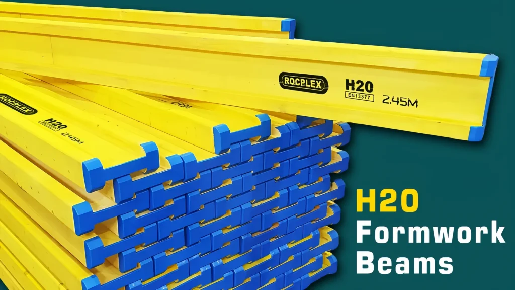
H20 Beams for Formwork in a Wall Pressure Plan
Wall formwork takes lateral pressure from fresh concrete. The facing passes that pressure to the timber beams, then to walings and ties in a tied system. A single-sided system needs its approved support frames and anchors instead.
Because pressure can vary with height, beam forces and tie forces must follow the stated pressure profile. A single beam capacity cannot establish an entire wall panel’s permitted pressure.
Doka’s Top 50 system varies H20 beam and steel waling spacing with the expected loads. That is a useful example of designing the assembly around pressure. It gives no automatic approval to a different beam, connection or tie arrangement.
The Mix and Placing Rate Belong in the Same Brief
How fast can the wall be poured? The answer comes from the approved pressure assessment for the actual mix and placing method. The crew needs that limit before concrete arrives.
ACI’s report on self-consolidating concrete form pressure identifies mix properties, casting rate and concrete temperature among the relevant inputs. It also links pressure decay to the concrete’s structural build-up at rest.
Consequently, an earlier pour with a different mix or temperature is weak proof for today’s rate. Keep the mix reference, expected temperature range, pressure limit and placing plan together. Then name the person who can stop or revise the pour when those inputs change.
This makes the pressure assumption visible to the crew that controls it. The beam layout and the placing plan remain part of the same decision.
Release the Layout Before Releasing the Pour
Before placing starts, compare the built form with the released drawing. Check the facing joints, all three slab grids or the wall’s beam, waling and tie arrangement. Also confirm that the installed components match the approved list.
The site check should end with a clear record of what was accepted and what still needs action. For example, a missing beam clip is easier to resolve while the deck remains unloaded. Then photograph the corrected detail and link it to the current drawing.
A drawing revision, site change and supply substitution should have one shared record. Otherwise, each team can hold a different version of the same pour.
Check the Contacts and the Temporary Load Cases
At each support, check the actual bearing, head fit and required restraint. Keep the load in the beam’s approved direction. Beam overlaps, end zones and connections must follow the named system detail. Also confirm the prop capacity at its installed extension and the ability of the base to carry the reaction.
Pouring adds changing work loads. A pile of reinforcement, a local heap of concrete or an unplanned work platform can alter the case. Therefore, keep the placing route and deck storage rules with the layout release.
For supported floors, the engineer must also consider the concrete’s age, the floors below and the propping sequence. A usable H20 beam does not decide when the new slab can support itself.
Doka’s early-stripping description retains temporary reshoring until the concrete has enough load-bearing strength. The release of beams for another pour must follow the approved stripping and reshoring plan.
Inspect H20 Beams for Formwork After Stripping
Stripping and handling can change a beam’s condition. A beam can leave the deck with new impact damage, a saw cut or an opened bond line. Inspect it after cleaning, before it joins the next released set.
We recommend three visible states in the yard: ready for use, held for review, and withdrawn from service. Each state needs an identified beam or batch, a reason and a responsible person. Then use the maker’s criteria to decide which state applies.
A beam held for review should stay out of the next pack until the issue is resolved. This keeps uncertainty away from the next pour’s material count.
A Crack Needs a Location and a Rule
The word “cracked” is too vague for a sound decision. Record whether the defect lies in a flange, the web, the flange-to-web joint or an end zone. Then record its direction, extent and the relevant maker’s rule.
Doka’s timber-beam manual uses different criteria for flange cracks, web damage, holes and flange-to-web separation. Its limits apply to its named beams. Use the confirmed criteria for the product we supply.
A loose joint or damaged flange needs review before further use. Filling or repainting cannot prove a restored load rating. Therefore, repairs need an approved method and a recorded release.
This is why a promised reuse count gives little help with one damaged beam. Its current condition and the permitted-use criteria govern the next decision.
Moisture Control Protects the Next Use
Moisture can affect wood size and strength. For example, Doka’s December 2024 H20 top manual requires value adjustments for changed use conditions or wood moisture above 20%. That threshold belongs to the stated Doka data. Our beam needs its own confirmed moisture basis.
End protection, coating and the bond do different jobs. Where end sealing or wax is specified, follow the approved care method. An intact end protector alone cannot prove a sound web or bond.
During storage, use level bearers and rain cover with airflow. Keep packs clear of ground moisture. Also limit damage during lifting and stripping. Follow the maker’s storage and repair rules.
The Next Deck Needs a Released Set
Before planning the next pour, count the beams ready for its approved layout. Also check that the required panels and support parts can reach the job with them.
We recommend measuring site efficiency through that complete set. Record cleaning time, inspection time, hold time, missing parts and setup corrections. Then trace recurring delays back to the task that causes them.
For example, a bond issue needs technical review. A missing support head needs a supply action. A pack waiting for identification needs better marking. Adding beams to stock may leave all three delays unresolved.
Measure the Hold Queue as Well as the Beam Stock
Track how long held beams wait for a decision and how often the same defect returns. Also record the reason for withdrawal. That shows whether damage arises during stripping, lifting, storage or an unapproved site change.
Use those records to improve handling and order planning. Keep the inspection record separate from the pour count. Together, they give a more useful history than a single claim about how many cycles a beam will last.
A repeat-use programme earns its value when a suitable set reaches the next approved layout on time.
Specify H20 Beams for Formwork with the Evidence Attached
For the supply order, name the product and the evidence the project needs. Request the applicable beam assessment, product data, bond and moisture basis, use instructions and damage criteria. Also identify the batch marks needed to keep the evidence attached to the delivered beams.
The flange grade, web build and bonded joint belong in that review. Ask which production checks support the declared performance and how test records relate to the offered product. The engineer can then compare the confirmed supply with the approved component list.
If the order includes the facing, keep its grade and load data in the same pack. Our formwork plywood range can be reviewed alongside the beams. That helps purchasing preserve the panel specification used in the layout.
What Changes Reopen the Review?
A new beam product, facing panel, tie system or prop arrangement can change the approved case. So can a different wall mix, a faster placing rate or a changed slab load. Record the proposed change and obtain the required review before it enters the pour.
Can another H20 beam use the same drawing? Only when the responsible designer accepts the offered beam data and system fit. A shared product name does not settle that decision.
Can a beam return simply because it passed the previous pour? The next release still needs its current condition checked. Handling and exposure between pours can change the evidence.
Send Us the H20 Beams for Formwork Brief
We supply ROCPLEX H20 slab formwork beams for review against your project requirements. Send the destination market, intended use, approved component specification, quantities, required documents and delivery plan.
For H20 beams for formwork, include the facing specification and the relevant layout revision with your enquiry. We can then quote the offered product and confirm which technical records are available. Your formwork designer retains control of the layout, loading and release decisions.
Request an H20 beam quotation and technical documents.
🌐 www.plywood.cn
✉️ roc@plywood.cn
📱 WhatsApp/Call: +86 15152013388
Post time: Oct-12-2026